Project / Demo
Solid-state Tesla coil
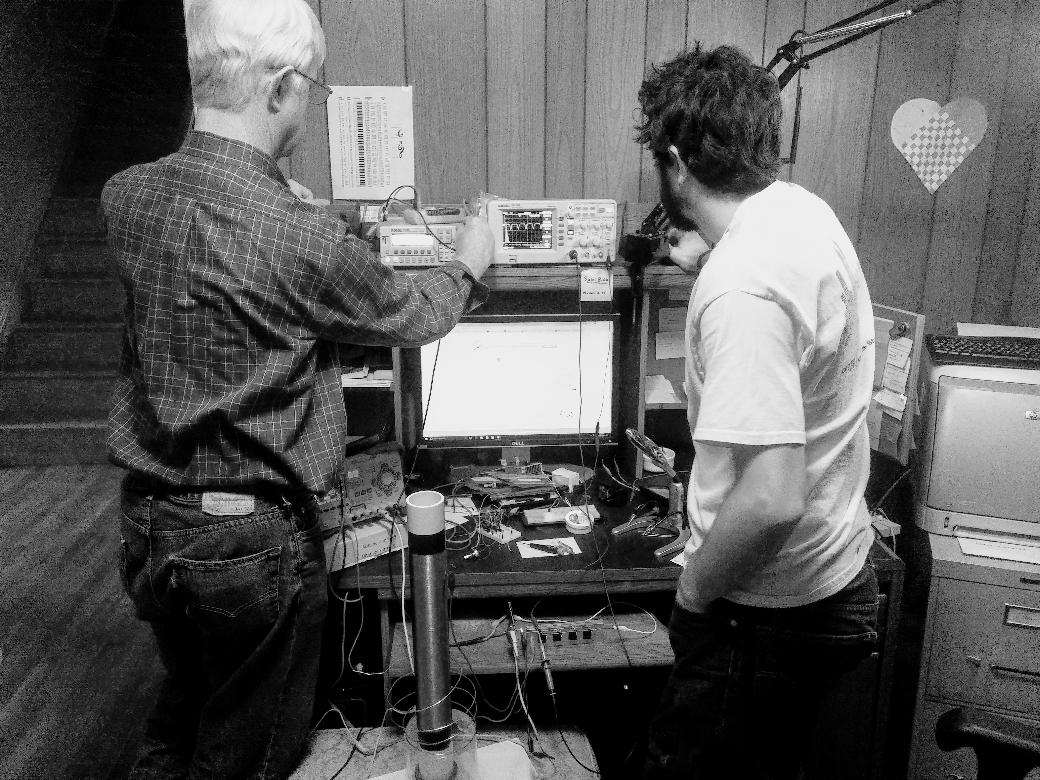
A solid-state, pulse-width-modulated, low-power Tesla coil — designed from scratch, built with my dad, and (eventually) able to sing.
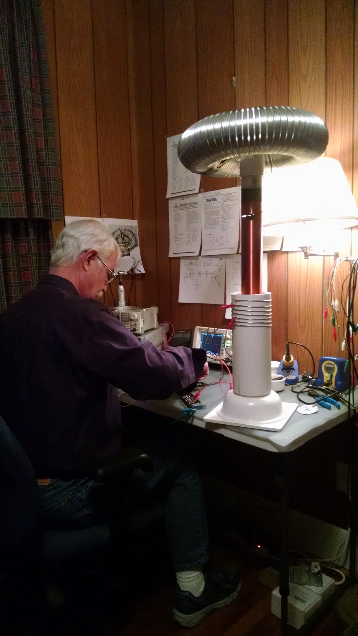
This page is a bit out of date — I finished the coil and made improvements to the design, including much better power transistors. I'll update the details when I get a chance.
I built my first Tesla coil after being inspired by Mehdi Sadaghdar's design. I tried copying his driving circuit but couldn't get it to operate at a high enough frequency (possibly a breadboard issue), so I decided to design the thing myself. There's still work to do to make a sparking, solid-state-driven, pulse-width-modulated, low-power Tesla coil — but it's well on its way. I can currently light bulbs held in my hand. I think the limit right now is that I'm not operating the power transistors in the switching regime, so I'm mostly just heating them up.
A Tesla what-now?
A Tesla coil is actually a special kind of transformer — a resonant transformer — that can provide voltage increases impossible with ordinary transformers. Unlike the transformers you hear about in a physics class, a Tesla coil wants a very weak mutual inductance between the primary and secondary (to mitigate the back-EMF from the discharging torus on the driving circuit). The voltage gain isn't simply the ratio of turns.
A toy model
I didn't have good intuition for how the parameters of a Tesla coil matter, so I made a toy model and studied how it depends on them. The model is two circuits coupled through the mutual inductance of the primary and secondary windings. Both sides are grounded to the same high-quality ground. (This is probably a poor model for a spark-gap coil, where the driving-circuit capacitance is large; here it's approximated as zero.)
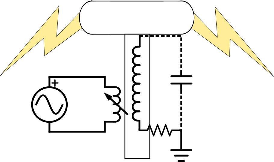
The two coupled differential equations from the circuit are
$$V(t)=L_1\dot{I}_1+kM\dot{I}_2$$
and
$$0=\frac{q_2}{C_2}+L_2\dot{I}_2+R_2 I_2-kM\dot{I}_1$$
where $M=\sqrt{L_1 L_2}$ is the mutual inductance of a perfectly coupled pair of coils. Assuming $V(t)=V_0 e^{i\omega t}$ lets us write
$$V_0=i\omega L_1 I_{1,0}-i\omega kM I_{2,0}$$
and
$$0=\frac{-i I_{2,0}}{\omega C_2}+i\omega L_2 I_{2,0}+R_2 I_{2,0}+i\omega kM I_{1,0}.$$
Doing the algebra, the impedance $Z=V_0/I_{2,0}$ is
$$Z=i\omega\left[\frac{L_1}{kM\omega^2 C_2}+kM-\frac{L_1 L_2}{kM}\right]-\frac{R L_1}{kM}.$$
From the impedance we get the resonant frequency by minimizing $Z$ with respect to $\omega$:
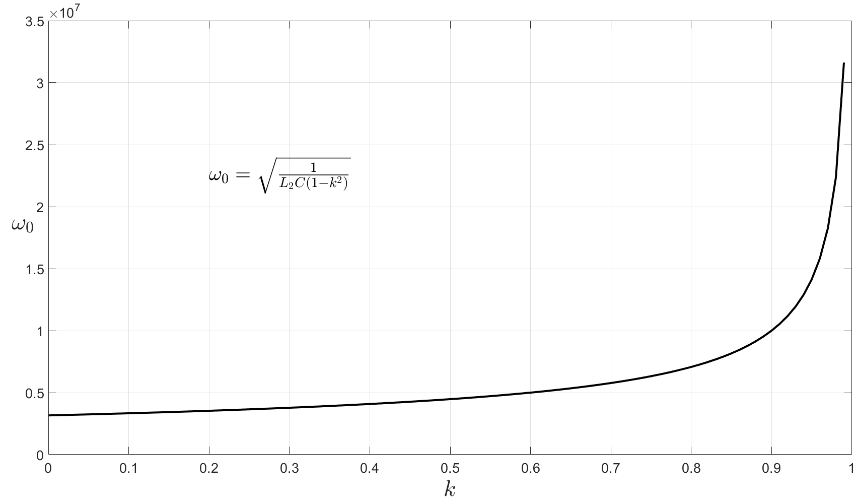
$$\omega=\sqrt{\frac{1}{L_2 C_2\left(1-k^2\right)}}\quad\left[\frac{\text{rad}}{\text{s}}\right]$$
or
$$\boxed{\,f_0=\frac{\omega}{2\pi}=\frac{1}{2\pi\sqrt{L_2 C_2\left(1-k^2\right)}}\ \ [\text{Hz}]\,}$$
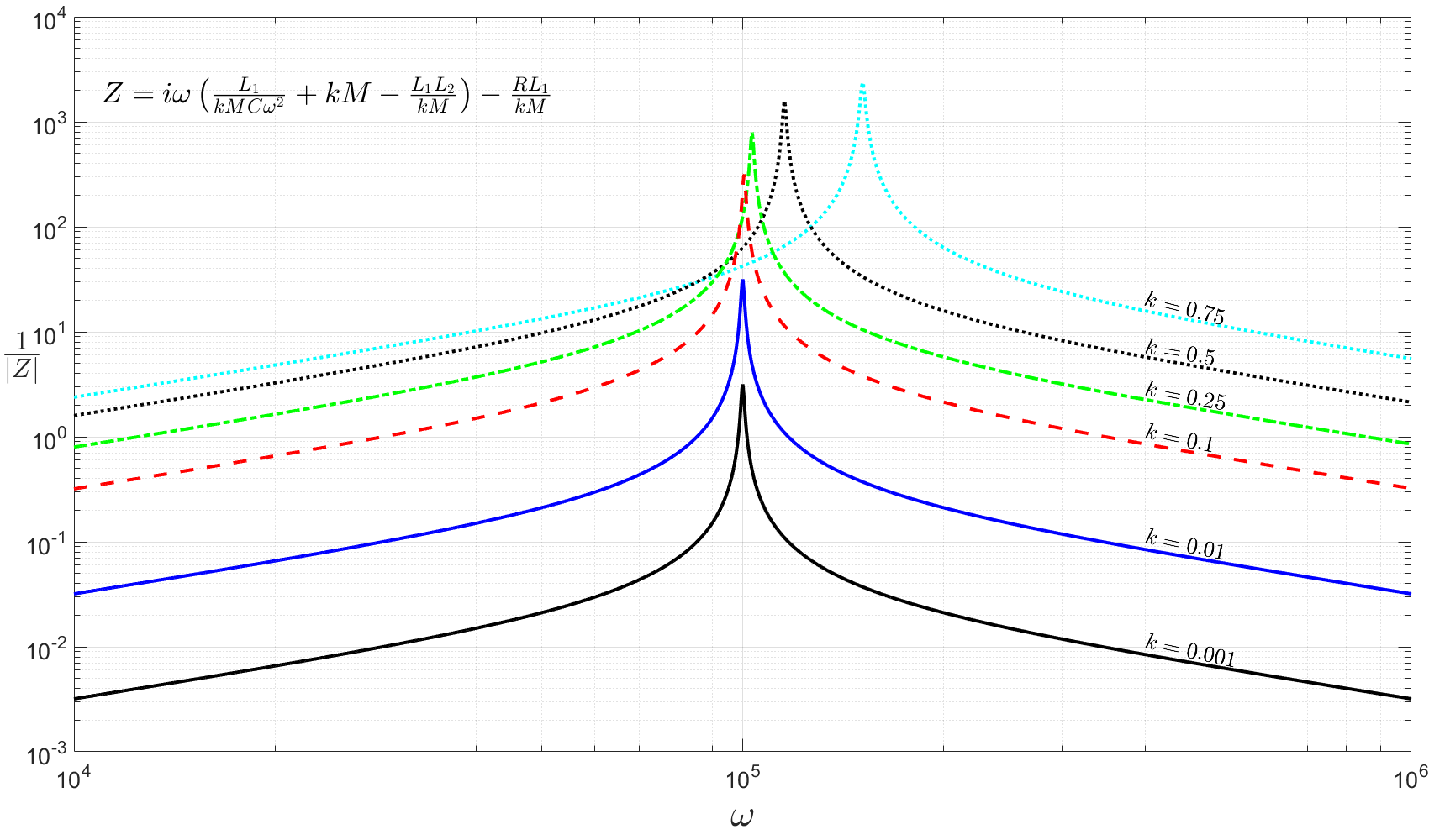
So the coupling constant $k$ tunes the resonant frequency of the coil. As Figure 1 shows, as long as $k$ is relatively small it barely affects the resonant frequency; likewise Figure 2 shows the quality factor is essentially unchanged for small $k$. That's the freedom that makes the whole design work: keep the coupling weak and the secondary rings at its own frequency, undisturbed.
The design
I designed the circuit in modules on different days to keep it manageable — which means it's not optimal, and getting the chunks to play nicely together took a while. Here is an interactive version of the circuit diagram.
The resonant frequency of my secondary coil and cap is very high (about 222 kHz), and the sparks come off after just a few oscillations. So if I switch the circuit on and off at an audible frequency — say 10 kHz — the sparks (and their noise) are emitted at that lower frequency, which the ear can hear. Drive the on/off according to an audio waveform, and the Tesla coil becomes a speaker.
To achieve that modulation I designed an oscillator with pulse-width modulation; varying the pulse width varies the power delivered to the coil. The oscillator is a comparator relaxation oscillator producing a triangle wave, fed into a second comparator whose threshold is set by the incoming audio signal. The output goes to the primary drive transistors through an op-amp that boosts the voltage enough to operate the transistors in saturation.

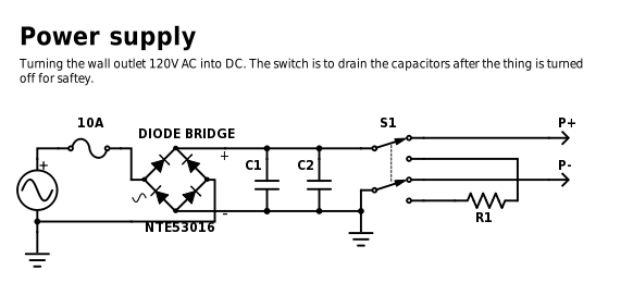
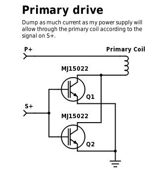
The brunt of the power comes from a home-made supply: a full-wave rectifier and smoothing capacitors, plus a fuse and a bleed resistor for safety (the caps hold charge long after unplugging). The physics says I want as much current through the primary coil as possible to produce a large magnetic field — which is why the high-frequency, high-current transistor choice is the hard part.
Building the thing
The first step was winding the secondary coil (with the invaluable help of my dad): about 1300 turns of 32 AWG wire on a 2-inch PVC pipe, with the ends held by a few winds of electrical tape.
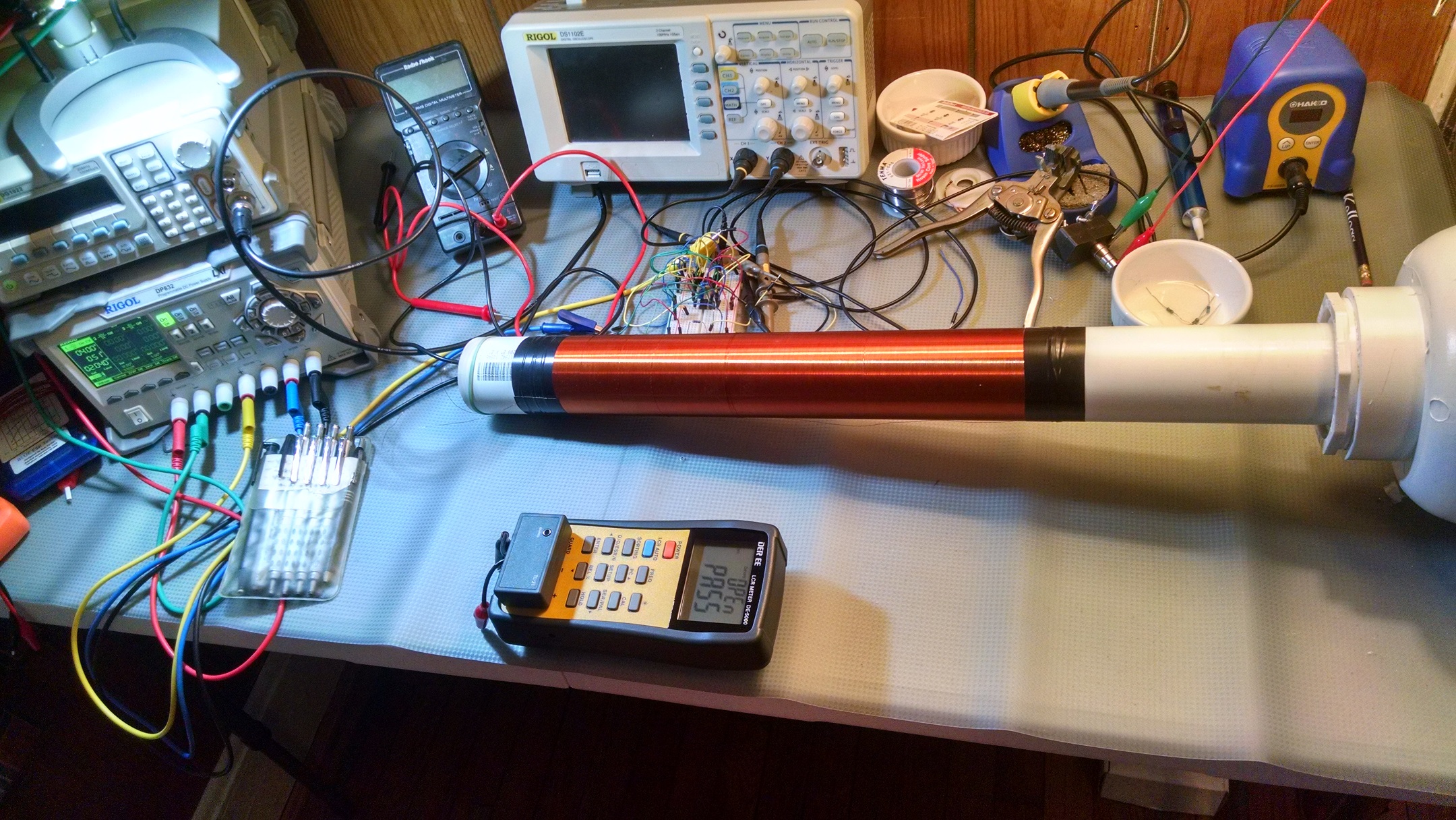
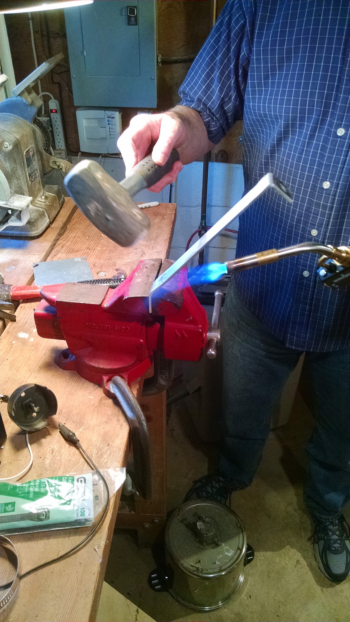
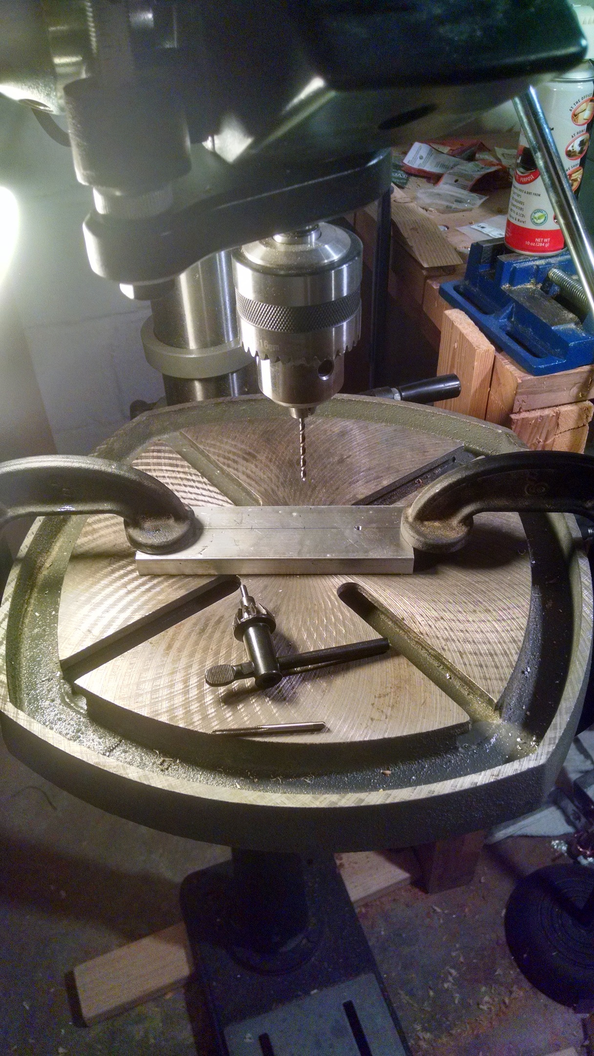
After the secondary was wound, I built the top toroid and mount — harder than it looks. The toroid is 3-inch dryer ducting; the PVC construction keeps everything modular, so the assembly comes apart easily and parts can be swapped without much work.
Safety
Do not attempt this without proper training. There are many hazards: not only extremely high voltages, but the arcs also produce ozone, which corrodes lung tissue and harms your health even at concentrations too low to smell. Only ever run a Tesla coil in a well-ventilated space.
Bill of parts
| Description | Qty | Part number | Provider | Unit price |
|---|---|---|---|---|
| 1kΩ resistor (R1, R4, R7) | 5 | 1.00KXBK-ND | Digi-Key | $0.84 |
| 10kΩ resistor (R2, R3, R8) | 3 | 10.0KXBK-ND | Digi-Key | $0.84 |
| 100Ω resistor (R5) | 1 | 100XBK-ND | Digi-Key | $0.84 |
| 2.7Ω resistor (R6) | 1 | RSA-2.7RCT-ND | Digi-Key | $1.85 |
| Multi-turn trim potentiometer (POT1) | 2 | A105870-ND | Digi-Key | $0.95 |
| Single-turn 100k potentiometer (POT2) | 1 | 987-1312-ND | Digi-Key | $0.67 |
| 100μF capacitor, 16V (C1, C4) | 2 | 493-10816-1-ND | Digi-Key | $0.66 |
| 10μF capacitor, 16V (C2, C5, C9) | 3 | P807-ND | Digi-Key | $0.23 |
| 100nF capacitor, 16V (C3, C6, C8) | 3 | 478-4873-ND | Digi-Key | $2.18 |
| 100pF capacitor, 10V (C7) | 1 | 338-3093-ND | Digi-Key | $1.52 |
| 10μH inductor, 2A (L1) | 1 | AIUR-03-100K-ND | Digi-Key | $1.72 |
| 7805 5V regulator (U1) | 1 | MC78L05BP-APMSCT-ND | Digi-Key | $0.49 |
| Dual comparator (U2, U3) | 2 | MCP6562-E/SN-ND | Digi-Key | $0.71 |
| MOSFET driver IC (U4) | 1 | 576-1211-ND | Digi-Key | $2.59 |
| Power MOSFET, 10A, 1200V (Q1–Q4) | 4 | SCT2450KEC-ND | Digi-Key | $4.89 |
| Op-amp (U5) | 1 | LM358ANFS-ND | Digi-Key | $0.42 |
Acknowledgements
Thanks to Mehdi Sadaghdar for the initial design, and to my dad for letting me use his test equipment and for his advice.